海洋立管作为海上油气生产的“大动脉”,在海洋油气资源开发中占有举足轻重的地位。随着现代海洋资源勘探和开采逐渐向着更深的水域靠近,面对更加复杂的海洋环境,传统钢质立管由于自身重量影响,使其对顶张力的要求不断增加,从而需要更大的海洋平台等条件提供支撑,这无疑于增加了石油开采的成本和难度。拥有质量轻、耐腐蚀,保温性好等优点的复合材料海洋立管提供了一个很好的解决方法[1]。国内外的一些学者对复合材料管道进行了相关研究,Amaechi等[2]借助ANSYS软件在6种不同工况下对复合材料立管进行了数值应力分析。Khudayarov等[3]考虑集中质量对复合材料管道的振动问题进行了相关研究。Wang等[4]基于临界载荷情况对FRP复合材料立管的管壁厚度和纤维方向进行了设计。研究表明复合材料海洋立管在深海石油开采中的应用具有巨大潜力[5]。
涡激振动是导致海洋立管疲劳破坏的最主要原因,由于其锁频共振会引起立管的大振幅振动,有时会直接导致立管的结构破坏,对海洋石油开采造成巨大的损失。由于复合材料立管的复杂结构特征,出现时间较晚等原因,对于复合材料海洋立管的涡激振动的研究相对较少。因此有必要对复合材料海洋立管的涡激振动特性进行相关的研究。Tan等[6]用工程模拟有限元软件ABQUS基于流固耦合的局部—整体分析方法研究了复合材料立管的结构性能。Rakshit等[7]用计算流体力学研究了中等雷诺数下,不同质量比、不同阻尼系数和不同顶张力对复合材料立管横向涡激振动的振幅和模态变化。
芮雪等[8]基于尾流振子模型和传递矩阵法对RTP管的横流向涡激振动特性进行了相关研究。在研究分析中,大多数学者都忽略了涡激振动对顺流向的影响,研究表明顺流向和横流向的耦合作用对立管的影响十分显著[9],因此有必要研究横流向和顺流向相互耦合的情况下复合材料立管的振动特性。
在实际的石油开采中,海洋管道通常携带气-液混合的能源,多相内流将导致管道的振动更复杂。Mamaghani等[10]建立了考虑不同两相内流的垂直管模型,并在此基础上进行了动态分析。Yang等[11]建立两相流柔性立管涡激振动预测模型,研究了海洋立管几何非线性的问题。Chang等[12]研究了黏弹性海洋立管在两相内流作用下,受气相体积分数、黏弹性系数等影响的动态响应特性。文献[13-15]等对多相内流立管在内外流耦合作用下的涡激振动响应进行了研究,发现管内两相内流会显著影响立管的涡激振动特性。马亚成等[16]基于计算结构力学和计算流体力学对多相内流作用下的倒置U形跨接管流致振动问题进行了研究。多相内流复合材料海洋立管的相关研究较少,有必要研究其振动特性。
复合材料立管由于其自身结构特性,其涡激振动动力学特性相比于金属材料立管会更加复杂。因此针对复合材料立管的涡激振动研究势在必行。本文建立了复合材料立管涡激振动的耦合振动控制方程,系统的分析了复合材料海洋立管在不同工作状况下立管的涡激振动特性。研究结果有助于深化对气-液两相输流复合材料立管涡激振动规律的认识,为复合材料立管的动力设计和优化提供理论基础和技术支持。
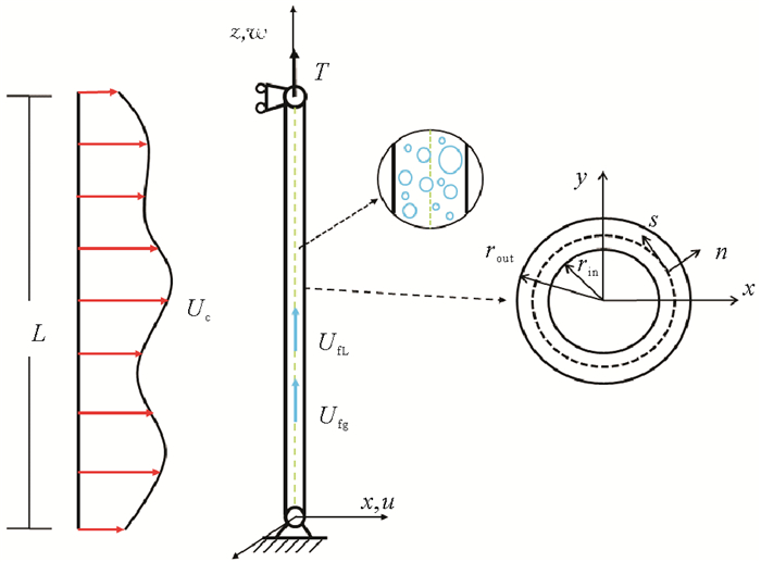
1 复合材料立管涡激振动耦合模型 1.1 复合材料海洋立管振动方程复合材料立管几何坐标示意图由图 1所示,取立管下部为坐标原点,以立管未变形时的轴线方向为z轴,向上为正,垂直于海流方向为y轴,平行于海流方向为x轴。立管纤维层的几何特征用局部坐标系s、n、z表示,θ为纤维取向角。u、v、w分别表示立管上任意一点在x、y、z方向上的位移。
|
图 1 复合材料海洋立管模型示意图 Fig. 1 Schematic diagram of composite marine riser model |
基于Bahaadini等[17]的文献,立管位移场设为:
| $ \begin{gathered} u(x, y, z ; t)=u_0(z ; t), \\v(x, y, z ; t)=v_0(z ; t), \\ w(x, y, z ; t)=-\frac{\partial v_0}{\partial z}\left[y(s)-n \frac{{\mathrm{d}} x}{{\mathrm{~d}} s}\right]- \\ \frac{\partial u_0}{\partial z}\left[x(s)+n \frac{{\mathrm{d}} y}{{\mathrm{~d}} s}\right] 。\end{gathered} $ | (1) |
式中u0、v0分别为立管轴线在x、y方向的振动位移。
由几何方程可以得应变—位移关系为:
| $ \begin{gathered} \varepsilon_z=\varepsilon_z^{(0)}+n \varepsilon_z^{(1)}, \\ \varepsilon_z^{(0)}=-y(s) \frac{\partial^2 v_0}{\partial z^2}-x(s) \frac{\partial^2 u_0}{\partial z^2} \\ \varepsilon_z^{(1)}=\frac{{\mathrm{d}} x}{{\mathrm{~d}} s} \frac{\partial^2 v_0}{\partial z^2}-\frac{{\mathrm{d}} y}{{\mathrm{~d}} s} \frac{\partial^2 u_0}{\partial z^2} 。\end{gathered} $ | (2) |
式中εz表示立管的应变。
复合材料海洋立管的应变能可表示为:
| $ U=\frac{1}{2} \int_0^L \oint_{{\mathrm{c}}} \int_{-\frac{h}{2}}^{\frac{h}{2}}\left(\bar{Q}_{22}-\frac{\bar{Q}_{12}^2}{\bar{Q}_{11}}\right)\left(\varepsilon_z^{(0)}+n \varepsilon_z^{(1)}\right)^2 {\mathrm{~d}} n {\mathrm{~d}} s {\mathrm{~d}} z。$ | (3) |
式中:h为立管纤维层厚;Qij(i, j=1, 2)为单层纤维材料刚度系数,i, j表示复合材料主轴方向,L为立管的长度。
复合材料海洋立管的动能E可表示为:
| $ \begin{gathered} E=\frac{1}{2} \int_0^L\left\{\left(m_{{\mathrm{v}}}+m_{{\mathrm{a}}}\right)\left[\left(\frac{\partial u_0}{\partial t}\right)^2+\left(\frac{\partial v_0}{\partial t}\right)^2\right]+\right. \\ {\left[m_{{\mathrm{fg}}} U_{{\mathrm{fg}}}^2+m_{{\mathrm{fL}}} U_{{\mathrm{fL}}}^2+m_{{\mathrm{fg}}}\left(\frac{\partial u_0}{\partial t}+U_{{\mathrm{fg}}} \frac{\partial u_0}{\partial z}\right)^2+\right.} \\ m_{{\mathrm{fg}}}\left(\frac{\partial v_0}{\partial t}+U_{{\mathrm{fg}}} \frac{\partial v_0}{\partial z}\right)^2+m_{{\mathrm{fL}}}\left(\frac{\partial u_0}{\partial t}+U_{{\mathrm{fL}}} \frac{\partial u_0}{\partial z}\right)^2+ \\ \left.\left.m_{{\mathrm{fL}}}\left(\frac{\partial v_0}{\partial t}+U_{{\mathrm{fL}}} \frac{\partial v_0}{\partial z}\right)^2\right]\right\} {\mathrm{d}} z。\end{gathered} $ | (4) |
式中:mv为单位长度的复合材料立管质量,且有mv=
结构阻尼,外部水动力及顶张力所做的功为:
| $ \begin{gathered} W=\int_0^L\left[-c \frac{\partial u_0}{\partial t} u_0-F_{{\mathrm{D}}} u_0+\frac{1}{2} T_{{\mathrm{e}}}\left(\frac{\partial u_0}{\partial z}\right)^2-\right. \\ \left.\quad c \frac{\partial v_0}{\partial t} v_0-F_{{\mathrm{L}}} v_0+\frac{1}{2} T_{{\mathrm{e}}}\left(\frac{\partial v_0}{\partial z}\right)^2\right] {\mathrm{d}} z。\end{gathered} $ | (5) |
式中:c为阻尼系数,一般取0.02;FD,FL分别为顺流向的拖曳力和横流向的升力。Te为轴力,表示为:
| $ T_{{\mathrm{e}}}=T-\left(m_{{\mathrm{v}}}+m_{{\mathrm{fg}}}+m_{{\mathrm{fL}}}-\rho_{{\mathrm{w}}} A\right) g(L-z) 。$ | (6) |
式中: T为顶张力,ρw为海水密度,A为立管外横截面积。
由哈密顿原理可得到复合材料海洋立管的顺流向和横流向的振动方程为:
| $ \begin{aligned} &a_{22} \frac{\partial^4 u_0}{\partial z^4}+a_{23} \frac{\partial^4 v_0}{\partial z^4}+\left(m_{{\mathrm{a}}}+m_{{\mathrm{v}}}+m_{{\mathrm{fg}}}+m_{{\mathrm{fL}}}\right) \frac{\partial^2 u_0}{\partial t^2}+ \\ &\left(c+c^{\prime}\right) \frac{\partial u_0}{\partial t}+\left(2 m_{{\mathrm{fg}}} U_{{\mathrm{fg}}}+2 m_{{\mathrm{fL}}} U_{{\mathrm{fL}}}\right) \frac{\partial^2 u_0}{\partial t \partial z}+ \\ &\left(m_{{\mathrm{fg}}} U_{{\mathrm{fg}}}^2+m_{{\mathrm{fL}}} U_{{\mathrm{fL}}}^2\right) \frac{\partial^2 u_0}{\partial z^2}-\frac{\partial}{\partial z}\left(T_e \frac{\partial u_0}{\partial z}\right)=F_{{\mathrm{D}}}, \\ &a_{33} \frac{\partial^4 v_0}{\partial z^4}+a_{23} \frac{\partial^4 u_0}{\partial z^4}+\left(m_{{\mathrm{a}}}+m_{{\mathrm{v}}}+m_{{\mathrm{fg}}}+m_{{\mathrm{fL}}}\right) \frac{\partial^2 v_0}{\partial t^2}+ \\ &\left(c+c^{\prime}\right) \frac{\partial v_0}{\partial t}+\left(2 m_{{\mathrm{fg}}} U_{{\mathrm{fg}}}+2 m_{{\mathrm{fL}}} U_{{\mathrm{fL}}}\right) \frac{\partial^2 v_0}{\partial t \partial z}+ \\ &\left(m_{{\mathrm{fg}}} U_{{\mathrm{fg}}}^2+m_{{\mathrm{fL}}} U_{{\mathrm{fL}}}^2\right) \frac{\partial^2 v_0}{\partial z^2}-\frac{\partial}{\partial z}\left(T_{{\mathrm{e}}} \frac{\partial v_0}{\partial z}\right)=F_{{\mathrm{L}}} 。\end{aligned} $ | (7) |
式中:
| $ \begin{gathered} a_{22}=\oint_c\left[K_{11} x^2+2 K_{14} x \frac{{\mathrm{d}} y}{{\mathrm{~d}} s}+K_{44}\left(\frac{{\mathrm{d}} y}{{\mathrm{~d}} s}\right)^2\right] {\mathrm{d}} s, \\ a_{33}=\oint_c\left[K_{11} y^2-2 K_{14} y \frac{{\mathrm{d}} x}{{\mathrm{~d}} s}+K_{44}\left(\frac{{\mathrm{d}} x}{{\mathrm{~d}} s}\right)^2\right] {\mathrm{d}} s, \\ a_{23}=\oint_c\left[K_{11} x y-K_{14}\left(x \frac{{\mathrm{d}} x}{{\mathrm{~d}} s}+y \frac{{\mathrm{d}} y}{{\mathrm{~d}} s}\right)-\right. \\ \left.K_{44} \frac{{\mathrm{d}} x}{{\mathrm{~d}} s} \frac{{\mathrm{d}} y}{{\mathrm{~d}} s}\right] {\mathrm{d}} s 。\end{gathered} $ | (8) |
式中:
| $ \begin{gathered} K_{11}=A_{22}-\frac{A_{12}^2}{A_{11}} ; K_{14}=D_{22}-\frac{B_{12}^2}{A_{11}}, \\ K_{44}=B_{22}-\frac{A_{12} B_{12}}{A_{11}} 。\\ \left\{A_{i j}, B_{i j}, D_{i j}\right\}=\sum\limits_{k=2}^N \int_{Z_{k-1}}^{Z_k} \bar{Q}_{i j}^{(k)}\left\{1, n, n^2\right\} {\mathrm{d}} n \\ i, j=1, 2, 6 。\end{gathered} $ | (9) |
式中Qij(k) (i, j=1, 2, 6)表示复合材料立管第k层在6个应力方向的材料系数,可由下式得出:
| $ \overline{{\boldsymbol{Q}}}_{i j}^{(k)}={\boldsymbol{T}}^{-1} {\boldsymbol{Q}}_{i j}^{(k)}\left({\boldsymbol{T}}^{-1}\right)^{{\mathrm{T}}} 。$ | (10) |
| $ {\boldsymbol{T}}=\left[\begin{array}{ccc} \cos ^2 \theta & \sin ^2 \theta & 2 \sin \theta \cos \theta \\ \sin ^2 \theta & \cos ^2 \theta & -2 \sin \theta \cos \theta \\ -\sin \theta \cos \theta & \sin \theta \cos \theta & \cos ^2 \theta-\sin ^2 \theta \end{array}\right]。$ | (11) |
| $ {{\boldsymbol{ Q}}}_{i j}^{(k)}=\left[\begin{array}{ccc} Q_{11}^{(k)} & Q_{12}^{(k)} & 0 \\ Q_{12}^{(k)} & Q_{22}^{(k)} & 0 \\ 0 & 0 & Q_{66}^{(k)} \end{array}\right]。$ | (12) |
式中:T为转置矩阵;第k层复合材料的弹性刚度系数表示为:
| $ Q_{11}=\frac{E_{11}}{1-\frac{E_{22}}{E_{11}} \nu_{12}^2}, Q_{12}=\frac{\nu_{12} E_{12}}{1-\frac{E_{22}}{E_{11}} \nu_{12}^2}, \\ Q_{22}=\frac{E_{22}}{1-\frac{E_{22}}{E_{11}} \nu_{12}^2}, Q_{66}=G_{12} 。$ | (13) |
式中:E11、E22分别为横向和纵向弹性模量;V12为泊松比;G12为剪切弹性模量。
此模型中,立管上下两端的边界条件为简支,边界条件表示为:
| $ \begin{aligned} &u_0(0, t)=0, \quad a_{22} \frac{\partial^2 u_0}{\partial z^2}(0, t)=0 ;\\ &u_0(L, t)=0, \quad a_{22} \frac{\partial^2 u_0}{\partial z^2}(L, t)=0 ;\\ &v_0(0, t)=0, \quad a_{33} \frac{\partial^2 v_0}{\partial z^2}(0, t)=0 ;\\ &v_0(L, t)=0, \quad a_{33} \frac{\partial^2 v_0}{\partial z^2}(L, t)=0 。\end{aligned} $ | (14) |
本文采用FACCHINETTI等[19]改进的半经验范德波尔尾流振子模型模拟流体与复合材料海洋立管的相互作用。改进的尾流振子以加速度为耦合向,控制方程为:
| $ \begin{aligned} &\frac{\partial^2 q_x}{\partial t^2}+\varepsilon_x \omega_{{\mathrm{s}}}\left(q_x-1\right) \frac{\partial q_x}{\partial t}+\left(2 \omega_{{\mathrm{s}}}\right)^2 q_x=\frac{A_x}{D} \frac{\partial^2 u_0}{\partial t^2}, \\ &\frac{\partial^2 q_y}{\partial t^2}+\varepsilon_y \omega_{{\mathrm{s}}}\left(q_y-1\right) \frac{\partial q_y}{\partial t}+\omega_{{\mathrm{s}}} q_y=\frac{A_y}{D} \frac{\partial^2 v_0}{\partial t^2} 。\end{aligned} $ | (15) |
式中:qx, qy为顺流向和横流向无量纲尾流振子参数;
根据莫里森方程得到立管顺流向和横流向涡激力表达式,并在此基础上对2个方向的力进行耦合。拖曳力和升力分别表示为:
| $ \begin{gathered} F_{{\mathrm{D}}}=\frac{1}{2} \rho D C_{{\mathrm{D}}} U_{{\mathrm{c}}} \sqrt{\left(U_{{\mathrm{c}}}-\frac{\partial u_0}{\partial t}\right)^2+\left(\frac{\partial v_0}{\partial t}\right)^2}, \\ F_{{\mathrm{L}}}=\frac{1}{2} \rho D C_{{\mathrm{L}}}\left(U_{{\mathrm{c}}}-\frac{\partial u_0}{\partial t}\right)^2。\end{gathered} $ | (16) |
式中:拖曳力系数和升力系数可用无量纲尾流振子参数表示为:CD=
气-液两相内流的相关参数参考Monette和Pettigrew等[20]学者的文献,定义单位长度立管内的气相体积Cfg、液相体积CfL、气相体积流量Qfg、液相体积流量QfL、空化率α、气体体积分数εg、滑移因子K的具体表达式为:
| $ \alpha=\frac{C_{{\mathrm{fg}}}}{C_{{\mathrm{fg}}}+C_{{\mathrm{fL}}}}, \varepsilon_{{\mathrm{g}}}=\frac{Q_{{\mathrm{fg}}}}{Q_{{\mathrm{fg}}}+Q_{{\mathrm{fL}}}}, K=\frac{U_{{\mathrm{fg}}}}{U_{{\mathrm{fL}}}} 。$ | (17) |
此外,滑移因子K也可以表示为空化率α和气体体积分数εg的函数:
| $ K=\frac{1-\alpha}{\alpha}=\left(\frac{\varepsilon_{{\mathrm{g}}}}{1-\varepsilon_{{\mathrm{g}}}}\right)^{1 / 2}。$ | (18) |
对复合材料立管的振动控制方程采用三次Hermit插值函数离散为N个单元,单元立管在x, y方向的位移u1, v1可以分别表示为:
| $ u_1={\boldsymbol{\varphi}}_x {\boldsymbol{d}}, \quad v_1={\boldsymbol{\varphi}}_y {\boldsymbol{d}}。$ | (19) |
式中:d表示立管单元位移,φ表示立管振动的形函数。他们分别为:
| $ {\boldsymbol{d}}^{{\mathrm{T}}}=\left[\begin{array}{llllllll} u_1 & \frac{{\mathrm{d}} u_1}{{\mathrm{~d}} z} & v_1 & \frac{{\mathrm{d}} v_1}{{\mathrm{~d}} z} & u_2 & \frac{{\mathrm{d}} u_2}{{\mathrm{~d}} z} & v_2 & \frac{{\mathrm{d}} v_2}{{\mathrm{~d}} z} \end{array}\right] 。$ | (20) |
令le为立管单元的长度,则有:
| $ \begin{array}{l} {\boldsymbol{\varphi}}_x= \\ {\left[1-\frac{3 z^2}{l_{{\mathrm{e}}}^2}+\frac{2 z^3}{l_{{\mathrm{e}}}^3} \quad z-\frac{2 z^2}{l_{{\mathrm{e}}}}+\frac{z^3}{l_{{\mathrm{e}}}^2} \quad 0 \quad 0 \quad \frac{3 z^2}{l_{{\mathrm{e}}}^2}-\frac{2 z^3}{l_{{\mathrm{e}}}^3}-\frac{z^2}{l_{{\mathrm{e}}}}+\frac{z^3}{l_{{\mathrm{e}}}^2} \quad 0 \quad 0\right]}, \\{\boldsymbol{\varphi}}_y=\\\left[\begin{array}{lll} 0 & 0 & 1-\frac{3 z^2}{l_{{\mathrm{e}}}^2}+\frac{2 z^3}{l_{{\mathrm{e}}}^3} \quad z-\frac{2 z^2}{l_{{\mathrm{e}}}}+\frac{z^3}{l_{{\mathrm{e}}}^2} \quad 0 \quad 0 \quad \frac{3 z^2}{l_{{\mathrm{e}}}^2}-\frac{2 z^3}{l_{{\mathrm{e}}}^3}-\frac{z^2}{l_{{\mathrm{e}}}}+\frac{z^3}{l_{{\mathrm{e}}}^2} \end{array}\right]。\end{array} $ | (21) |
使用伽辽金加权余量法对立管的耦合振动方程进行积分变换,形成立管单元的振动方程:
| $ \left[{\boldsymbol{M}}_{{\mathrm{e}}}\right]\{\ddot{{\boldsymbol{d}}}\}+\left[{\boldsymbol{C}}_{{\mathrm{e}}}\right]\{\dot{{\boldsymbol{d}}}\}+\left[{\boldsymbol{K}}_{{\mathrm{e}}}\right]\{{\boldsymbol{d}}\}=\left\{{\boldsymbol{F}}_{{\mathrm{e}}}\right\} 。$ | (22) |
式中:Me、Ce、Ke、Fe分别为立管单元质量矩阵、阻尼矩阵、刚度矩阵和载荷矩阵。
随后对各单元矩阵进行组装,可得到立管的矩阵形式的总体振动控制方程为:
| $ {{\boldsymbol{M \ddot{D}} }}+{{\boldsymbol{ C \dot{D}}}}+{{\boldsymbol{K D }}}={{\boldsymbol{F }}}。$ | (23) |
式中:M、C、K、F分别表示立管整体的质量矩阵、阻尼矩阵、刚度矩阵和载荷矩阵。
采用MATLAB软件编程,使用Newmark-β法和四阶Runge-Kutta法分别对立管振动方程和尾流振子控制方程在立管长度方向和时域方向进行逐步耦合积分求解,得到复合材料海洋立管在各种条件下横流向和顺流向的位移、速度、加速度响应。并在此基础上,对立管其他振动特性进行分析。
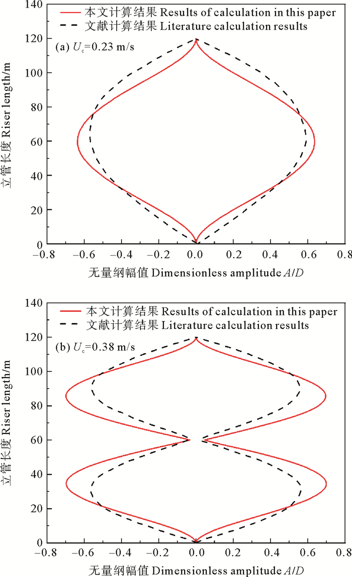
2.2 模型验证为验证该模型的有效性,设内部流体流速为零,与Yamamoto等[21]使用CFD方法计算的结果进行对比,计算所用参数如表 1所示,均匀海流流速分别取0.23和0.38 m/s时计算出的结果如图 2所示。横流向的无量纲最大位移包络图相近,不同外流下立管的振动形态也能很好的与文献吻合,证明了该模型的可靠性。
|
|
表 1 模型验证相关参数 Table 1 Model validation related parameters |
|
图 2 不同海流流速下立管横向位移包络图对比 Fig. 2 Comparison of lateral displacement envelope of riser under different current velocity |
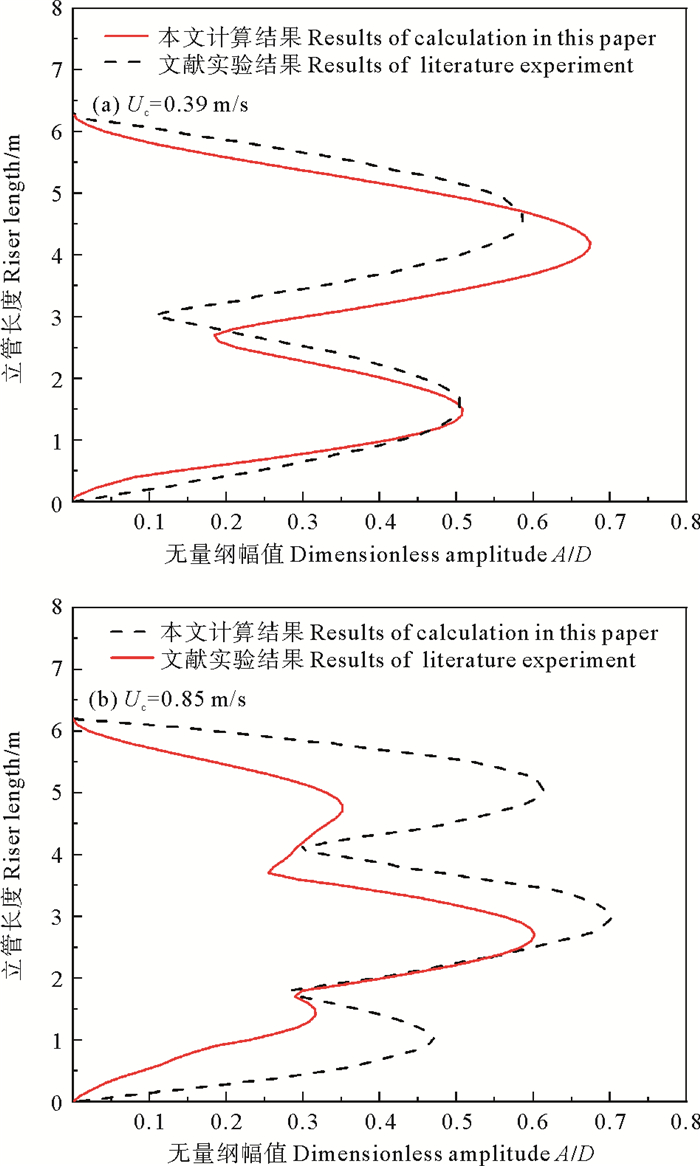
为进一步验证该模型的有效性,与郭海燕等[22]做的实验数据进行对比。根据文献[22]顶张力取53.3 N,立管外部水流流速分别为0.39和0.85 m/s,其他相关参数如表 2所示,对比图 3立管无量纲位移包络图。可以看到,本模型与实验所得的结果在外流速度为0.39 m/s时能很好的吻合,在外流速度为0.85 m/s时虽然有一定的误差,但也能正确反映出立管的振动形态,再次证明了本文使用的模型对海洋立管的涡激振动的分析是有效的。
|
|
表 2 实验立管参数 Table 2 Experimental riser parameters |
|
图 3 不同外流流速下立管位移响应包络图 Fig. 3 Envelope diagram of riser displacement response under different outflow velocities |
参考文献[23]和其他相关标准,分析复合材料海洋立管的涡激振动时选取模型的基本参数如表 3所示。
2.3.1 液相流速对复合材料海洋立管涡激振动影响结合实际工况,取气体体积分数εg=0.4,液相流速范围为0~10 m/s。均匀海流流速为0.5 m/s, 纤维层厚度取2 mm,纤维层数为10层,纤维取向角为±60°,其余参数由表 3所示。
图 4为液相流速分别为1、4、7、10 m/s时立管横流向与顺流向的涡激振动振动位移包络图。由图 4可知,随着液相流速的增大,立管的振动模态随之增加,并且顺流向的振动模态高于横流向的振动模态。当液相流速由1 m/s增加到4 m/s时,立管的振动模态发生改变,此时横流向的最大振动位移也随之增大,并且大于顺流向的振动位移;液相流速由4 m/s增加到10 m/s时,立管的振动模态均为6阶,此时横流向的最大振动位移与液相流速呈负相关。由图 4(b)可知立管顺流向的振动平衡位置的偏移量随着液相流速的增大而逐渐增大,并且偏移速率与液相流速呈正相关。因此立管内流对振动模态和响应幅值有很大影响,在分析复合材料立管的涡激振动时,顺流向和横流向的振动特性都应重视。

|
图 4 不同液相速度下立管位移最大包络图对比 Fig. 4 Comparison of maximum envelope diagrams of riser displacement at different liquid phase velocities |
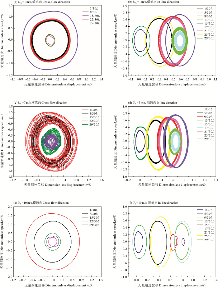
图 5为不同液相流速下复合材料立管涡激振动时不同位置的相轨迹图。由图 5可知,随着液相流速的增大,立管的振动响应由周期性转化为非周期性,再变为周期性,相轨迹图近似为圆或者椭圆。当液相流速为1和10 m/s时,立管横流向和顺流向各位置的相图为单个闭环,因此为周期响应;而当液相流速为7 m/s时,立管顺流向各位置相图接近单个闭环,但横流向各位置的相图由很多条封闭曲线组成,因此立管的振动为准周期或者混沌响应。对比所有相轨迹图可以发现液相流速为10 m/s时,复合材料立管的运动周期性最强。此外,复合材料立管在振动时,不同位置的周期性程度不同,立管中点对称位置的相轨迹接近,说明立管中心对称位置的振动形态相似;在靠近立管两端和中点位置,立管的振动更具周期性。
|
图 5 不同液相流速下立管不同位置相轨迹对比 Fig. 5 Comparison of phase trajectories at different positions of risers at different liquid flow rates |
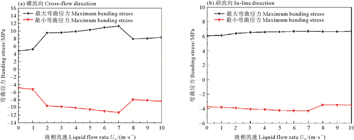
图 6为不同液相流速下横流向与顺流向涡激振动时的弯曲应力变化对比图,由图可知:当液相流速由0逐渐增加到7 m/s时,横流向的最大和最小弯曲应力随之增加,并在液相流速由1 m/s增加到2 m/s时,横流向的最大和最小弯曲应力“跳跃”增加;当液相流速由7 m/s增加到10 m/s时,横流向的最大和最小弯曲应力先“跳跃”减小,再逐渐稳定增加。顺流向的弯曲应力受液相流速影响较小。液相流速大于1 m/s时,横流向的弯曲应力始终大于顺流向。
|
图 6 不同液相流速下弯曲应力对比 Fig. 6 Comparison of bending stresses at different fluid velocities |
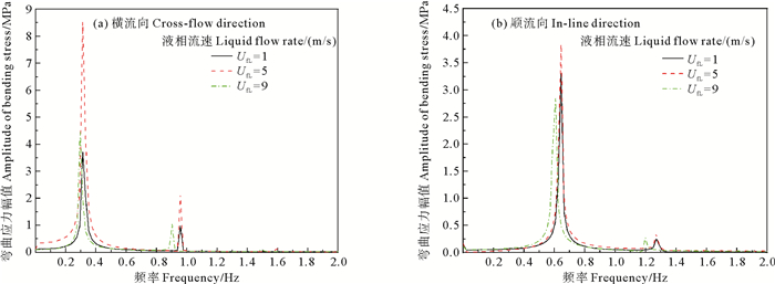
图 7、8分别为立管中部弯曲应力的时程曲线图和对应的幅频曲线图。不同液相流速下立管所受的弯曲应力不同,UfL为5 m/s时立管横流向和顺流向的弯曲应力大于其它流速。UfL的增大对立管振动频率影响不大。立管顺流向的振动频率约为横流向的2倍,均为多频带响应。在研究复合材料立管的疲劳破坏时,顺流向和横流向应同时重点关注。

|
图 7 不同液相流速下立管中部弯曲应力时程对比 Fig. 7 Comparison of the time history of bending stress in the middle of the riser at different liquid flow rates |
|
图 8 不同液相流速下立管中部弯曲应力幅频曲线对比 Fig. 8 Comparison of amplitude-frequency curves of bending stress in the middle of riser under different liquid flow rates |
为了研究气体体积分数对复合材料立管涡激振动机理的影响,取液相流速为4 m/s,气体体积分数εg的变化范围为0~0.9。均匀海流流速为0.5 m/s, 纤维层厚度取3 mm,纤维层数为8层,纤维取向角为60°,其余参数由表 3所示。
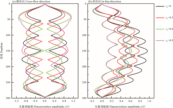
图 9为不同气体体积分数下复合材料海洋立管横流向和顺流向涡激振动时的最大位移包络图对比情况。由图(a)可知,当εg=0或εg=0.3时,立管的振动位移在中部较大;而当εg=0.6或εg=0.9时,立管顶端的振动位移大于立管中部。由图(b)可知,复合材料立管在顺流向的偏移量随着εg的增大而逐渐缩小,并且偏移量的减小趋势也逐渐减小,当εg=0.6或εg=0.9时,立管的偏移量基本一致。对比横流向和顺流向的振动位移包络图可知,气体体积分数对复合材料立管的振动模态有很大的影响,横流向的振动模态随着气体体积分数的增加由6阶逐渐降低到3阶,顺流向的振动模态随着气体体积分数的增加由9阶逐渐降到7阶,可以看出顺流向的振动模态是大于横流向的,同时,横流向的振动位移依旧大于顺流向的振动位移。
|
图 9 不同气体体积分数下立管位移最大包络图对比 Fig. 9 Comparison of maximum envelope diagrams of standpipe displacement under different gas volume fractions |
图 10为不同气体体积分数下复合材料海洋立管横流向和顺流向涡激振动时,沿轴向不同位置的相轨迹对比图,由相图可知,关于海洋立管中点对称的位置相轨迹响应相似,当εg=0或εg=0.3时,立管横流向的相轨迹图由多条闭合曲线组成,表现为非周期运动,顺流向的相轨迹图接近单条闭合圆环,表现为周期运动。当εg=0.6或εg=0.9时,复合材料海洋立管横流向各位置的涡激振动相轨迹发生了很多的变化,不再是单个闭合圆环。由图 10(e)和(f)可知,以立管顶部为基准,1/30L和29/30L位置的相轨迹为近似椭圆形,8/30L位置的相轨迹图为“卧”8字形,22/30L位置的相轨迹图交替形成为3个圆环,这是由于在此位置速度发生了突变,顺流向的相轨迹图为单个圆环,均为周期运动。由图 10(g)和(h)可以看出,立管横流向各位置的相轨迹图由2条或者3条闭合曲线组成,顺流向相轨迹图由多条闭合圆环组成,为倍周期运动。对比不同εg下立管振动位移最小处的相轨迹(绿色线条显示)发现,复合材料立管涡激振动位移最小处的响应周期性远低于其他位置,且表现为混沌特性运动或者是速度发生突变的运动。
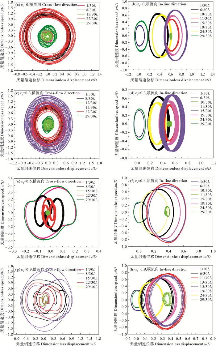
|
图 10 不同气体体积分数下立管不同位置相轨迹对比 Fig. 10 Comparison of phase trajectories at different positions of risers under different gas volume fractions |
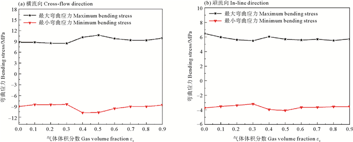
图 11为不同气体体积分数下复合材料立管涡激振动的弯曲应力对比图,横流向的最大和最小弯曲应力在εg从0增加到0.3时变化较小,当εg从0.3增加到0.7时最大和最小弯曲应力逐渐增大,再缓慢减小,随后随着εg增加到0.9时再稍微增大。顺流向的最大和最小弯曲应力在εg从0增加到0.5时先逐渐减小,在εg为0.3时发生“反转”(即增加),随后到0.4再减小,当εg从0.5增加到0.9时最大和最小弯曲应力变化较小,上述弯曲应力发生变化是因为气体体积分数的改变导致复合材料立管的振动模态发生了变化。同时,横流向的弯曲应力的绝对值大于顺流向。
|
图 11 不同气体体积分数下立管弯曲应力对比 Fig. 11 Comparison of bending stress of riser under different gas volume fractions |
取气体体积分数εg为0.2,液相流速为4 m/s,均匀海流速度为0.5 m/s, 纤维厚度为3 mm, 纤维层数为10层,纤维取向角取值为0°~90°,其他相关参数参照表 3。
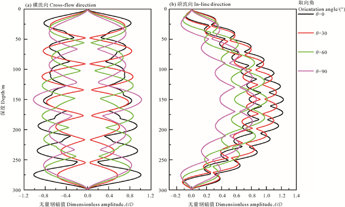
图 12为不同纤维取向角下复合材料海洋立管涡激振动的最大位移包络图,在不同的纤维取向角下,复合材料海洋立管横流向和顺流向涡激振动的振动模态和振动幅值会发生较大改变。立管的振动模态随着θ的增大逐渐减小,而且横流向的振动模态低于顺流向。由图 12(a)可以看出,复合材料海洋立管在涡激振动时相同模态下,立管的振动位移随着θ的增大而减小,当θ的改变激发出低阶模态时,立管的振动位移会显著增大,当θ接近90°时,这种现象又会逐渐减小。由图 12(b)可以看出,随着θ的增大,立管在顺流方向的偏移量逐渐减小。
|
图 12 不同纤维取向角下立管位移最大包络图对比 Fig. 12 Comparison of maximum envelope diagrams of riser displacement under different fiber orientation angles |
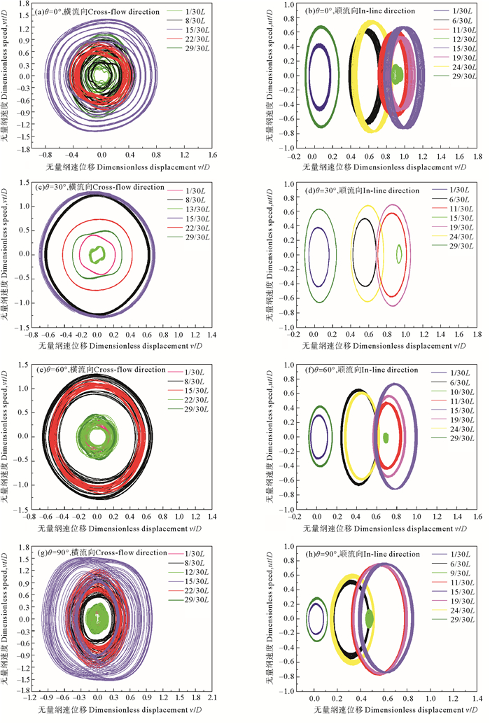
图 13为不同纤维取向角下复合材料海洋立管各位置涡激振动的相轨迹图。由图 13可知,立管中点对称位置的每对相轨迹图相似,说明立管的涡激振动有很强的对称性。此外,不同的θ对立管不同位置运动的周期性有很大影响: 当θ=0或θ=90°时,立管横流向各位置的相轨迹表现为准周期或者混沌特性,顺流向除振动位移最小处为混沌响应外均为周期响应;当θ=30°或θ=60°时,立管横流向和顺流向除振动位移最小处为非周期运动外,均为周期响应,并且当θ=30°时,立管的涡激振动周期性最强。
|
图 13 不同纤维取向角下立管不同位置相轨迹对比 Fig. 13 Comparison of phase trajectories at different positions of risers under different orientation |
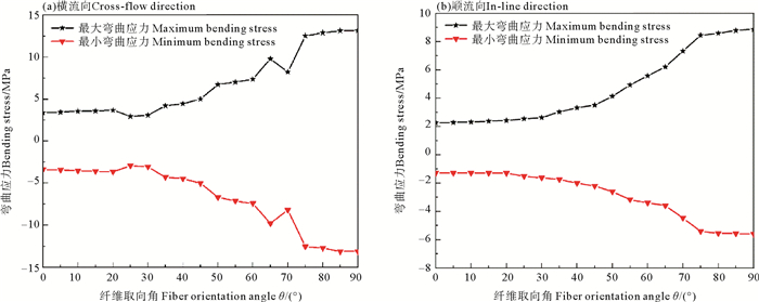
图 14为不同纤维取向角下复合材料海洋立管涡激振动的弯曲应力对比图。对比发现,立管横流向的弯曲应力对θ的改变相对于顺流向更敏感,当θ由0增加到20°时,横流向和顺流向最大和最小弯曲应力稳定变化,当θ由20°增加到65°时,立管横流向最大和最小弯曲应力先减小再增加,顺流向的最大和最小弯曲应力稳定增加;当θ由65°增加90°时,立管横流向最大和最小弯曲应力发生“跳跃”减小和“跳跃”增加,随后再趋于稳定,顺流向最大和最小弯曲应力先稳定增加后趋于稳定。横流向的弯曲应力的绝对值大于顺流向。
|
图 14 不同纤维取向角下弯曲应力对比 Fig. 14 Comparison of bending stress under different fiber orientation angles |
图 15、16分别为不同纤维取向角下立管中部的弯曲应力时程曲线图和幅频曲线图。由图可知,随着θ的增大,立管中部2个方向的弯曲应力幅值也随之增大。同时,θ对立管的振动频率影响较小,但顺流向的振动频率约为横流向的2倍,均为多频带响应。说明在研究复合材料海洋立管的疲劳破坏时, 应同时重点考虑顺流向和横流向。

|
图 15 不同纤维取向角下立管中部弯曲应力时程对比 Fig. 15 Time history comparison of bending stress in the middle of riser at different fiber orientation angles |
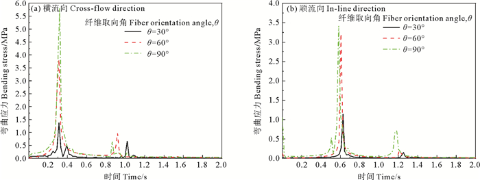
|
图 16 不同纤维取向角下立管中部弯曲应力幅频曲线对比 Fig. 16 Comparison of amplitude-frequency curves of bending stress in the middle of riser under different fiber orientation angles |
建立了复合材料立管的耦合振动控制方程,并与相关模型实验结果对比,验证了其有效性。分析了复合材料立管在油-气两相内流及外流等共同作用下,横流向和顺流向耦合涡激振动特性。得到以下结论:
(1) 随着液相流速的增大,立管的振动模态和横流向的最大振动位移随之增加,顺流向的平衡位置偏移量与液相流速呈正相关;气体体积分数的改变与复合材料海洋立管的振动形态变化和顺流向的偏移量呈负相关,同时气体体积分数的变化使得沿立管轴向各位置的最大振动位移各不相同;立管的振动形态和顺流向的偏移量随着纤维取向角的增大逐渐减小。
(2) 复合材料海洋立管不同位置的周期性程度不同,在关于立管中点对称位置上的涡激振动响应特征相似;顺流向的运动周期性强于横流向;立管涡激振动位移最小处的运动多为准周期或者混沌形式,周期性低于其他位置。
(3) 复合材料海洋立管横流向的弯曲应力对液相流速和纤维取向角的改变更加敏感;气体体积分数的变化对横流向和顺流向的弯曲应力影响较小;横流向的弯曲应力值大于顺流向的弯曲应力值,但顺流向的振动频率约为横流向2倍,因此在研究立管的疲劳破坏时应同时重点考虑顺流向和横流向。
| [1] |
Ochoa O, Salama M. Offshore composites: Transition barriers to an enabling technology[J]. Composites Science and Technology, 2005, 65: 2588-2596. DOI:10.1016/j.compscitech.2005.05.019 (  0) 0) |
| [2] |
Amaechi C V, Gillett N, Odijie A C, et al. Composite risers for deep waters using a numerical modelling approach[J]. Composite Structures, 2019, 210: 486-499. DOI:10.1016/j.compstruct.2018.11.057 (  0) 0) |
| [3] |
Khudayarov B A, Komilova K M. Vibration and dynamic stability of composite pipelines conveying a two-phase fluid flows[J]. Engineering Failure Analysis, 2019, 104: 500-512. DOI:10.1016/j.engfailanal.2019.06.025 (  0) 0) |
| [4] |
Wang C, Shankar K, Morozov E V. Tailored local design of deep sea FRP composite risers[J]. Advanced Composite Materials, 2015, 24(4): 375-397. DOI:10.1080/09243046.2014.898438 (  0) 0) |
| [5] |
Pham D, Sridhar N, Qian X, et al. A review on design, manufacture and mechanics of composite risers[J]. Ocean Engineering, 2016, 112: 82-96. DOI:10.1016/j.oceaneng.2015.12.004 (  0) 0) |
| [6] |
Tan L B, Chen Y, Jaiman R K, et al. Coupled fluid-structure simulations for evaluating a performance of full-scale deepwater composite riser[J]. Ocean Engineering, 2015, 94: 19-35. DOI:10.1016/j.oceaneng.2014.11.007 (  0) 0) |
| [7] |
Rakshit T, Atluri S, Dalton C. VIV of a composite riser at moderate reynolds number using CFD[J]. Journal of Offshore Mechanics and Arctic Engineering-Transactions of the ASME, 2008, 130: 110091. (  0) 0) |
| [8] |
芮雪, 陈东阳, 王国平. 海洋热塑性增强管(RTP)涡激振动数值计算[J]. 力学学报, 2020, 52(1): 235-246. Rui X, Chen D Y, Wang G P. Numerical calculation of vortex-induced vibration of Reinforced Thermoplastic Pipe[J]. Chinese Journal of Theoretical and Applied Mechanics, 2020, 52(1): 235-246. (  0) 0) |
| [9] |
柳军, 郭晓强, 刘清友. 考虑顺流向和横流向耦合作用的海洋立管涡激振动响应特性[J]. 石油学报, 2019, 40(10): 1270-1280. Liu J, Guo X Q, Liu Q Y. Vortex induced vibration response characteristics of marine riser considering the in-line and cross-flow coupling effect[J]. Acta Petrolei Sinica, 2019, 40(10): 1270-1280. DOI:10.7623/syxb201910012 (  0) 0) |
| [10] |
Ebrahimi-Mamaghani A, Sotudeh-Gharebagh R, Zarghami R, et al. Dynamics of two-phase flow in vertical pipes[J]. Journal of Fluids and Structures, 2019, 87: 150-173. DOI:10.1016/j.jfluidstructs.2019.03.010 (  0) 0) |
| [11] |
Yang W W, Chang X P, Gou R Y. Nonlinear vortex-induced vibration dynamics of a flexible pipe conveying two-phase flow[J]. Advances in Mechanical Engineering, 2019, 11(10): 2072157280. (  0) 0) |
| [12] |
Chang X P, Fan J M, Yang W W, et al. In-Line and cross-flow coupling vibration response characteristics of a marine viscoelastic riser subjected to two-phase internal flow[J]. Shock and Vibration, 2021, 2021: 1-27. (  0) 0) |
| [13] |
马天麒, 顾继俊, 孙旭. 内输多相流与绕流耦合作用下立管非线性振动[J]. 振动与冲击, 2018, 37(23): 15-23. Ma T Q, Gu J J, Sun X. Nonlinear vibration of a riser under inter-action between internal multi-phase flow and cross flow[J]. Journal of Vibration and Shock, 2018, 37(23): 15-23. (  0) 0) |
| [14] |
Ma T, Gu J, Duan M. Dynamic response of pipes conveying two-phase flow based on Timoshenko beam model[J]. Marine Systems & Ocean Technology, 2017(6): 1-14. (  0) 0) |
| [15] |
陈阳波. 深海气液混输立管涡激振动及疲劳损伤分析[D]. 杭州: 中国计量大学, 2016. Chen Y B. Vortex-Induced Vibration and Fatigue Damage Analysis of Deep Sea Gas-Liquid Mixed Transport Riser[D]. Hangzhou: China Jiliang University, 2016. (  0) 0) |
| [16] |
马亚成, 唐文勇, 王晋. 多相流作用下水下刚性跨接管流致振动特性数值模拟方法研究[J]. 船海工程, 2014, 43(4): 96-100. Ma Y C, Tang W Y, Wang J. On the numerical simulation methods of internal multiphase flow-induced vibration in subsea rijid jumper[J]. Ship & Ocean Engineering, 2014, 43(4): 96-100. (  0) 0) |
| [17] |
Bahaadini R, Dashtbayazi M R, Hosseini M, et al. Stability analysis of composite thin-walled pipes conveying fluid[J]. Ocean Engineering, 2018, 160: 311-323. DOI:10.1016/j.oceaneng.2018.04.061 (  0) 0) |
| [18] |
Librescu L, Oh S Y, Song O. Spinning thin-walled beams made of functionally graded materials: Modeling, vibration and instability[J]. European Journal of Mechanics-A/Solids, 2004, 23(3): 499-515. DOI:10.1016/j.euromechsol.2003.12.003 (  0) 0) |
| [19] |
Facchinetti M L, de Langre E, Biolley F. Coupling of structure and wake oscillators in vortex-induced vibrations[J]. Journal of Fluids and Structures, 2004, 19(2): 123-140. DOI:10.1016/j.jfluidstructs.2003.12.004 (  0) 0) |
| [20] |
Monette C, Pettigrew M J. Fluidelastic instability of flexible tubes subjected to two-phase internal flow[J]. Journal of Fluids and Structures, 2004, 19(7): 943-956. (  0) 0) |
| [21] |
Yamamoto C T, Meneghini J R, Saltara F, et al. Numerical simulations of vortex-induced vibration on flexible cylinders[J]. Journal of Fluids and Structures, 2004, 19(4): 467-489. (  0) 0) |
| [22] |
郭海燕, 牛建杰, 李效民. 海洋立管涡激振动模型的实验验证[J]. 中国海洋大学学报(自然科学版), 2015, 45(6): 108-115. Guo H Y, Niu J J, Li X M. Experimental verification of vortex-induced vibration model of marine riser[J]. Periodical of Ocean University of China, 2015, 45(6): 108-115. (  0) 0) |
| [23] |
Silva R F D, Teófilo F A F, Parente E, et al. Optimization of composite catenary risers[J]. Marine Structures, 2013, 33: 1-20. (  0) 0) |
 2022, Vol. 52

